
Assembled-Kit Assembly
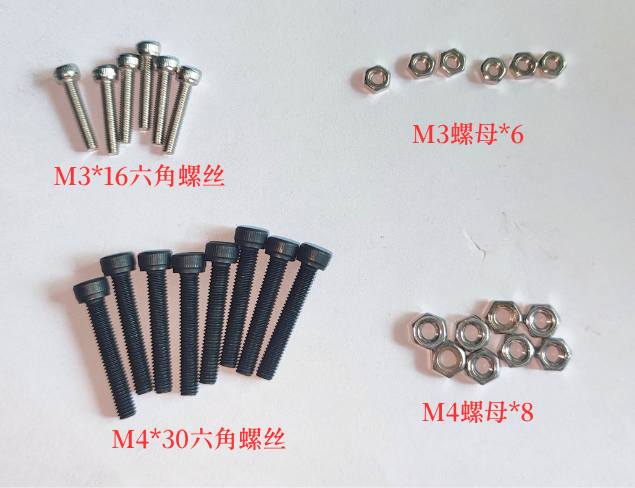
Parts List
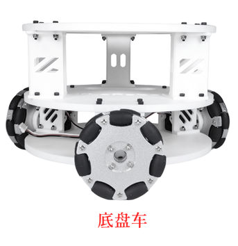
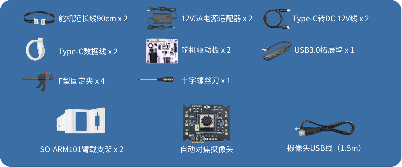
Install the Chassis Car
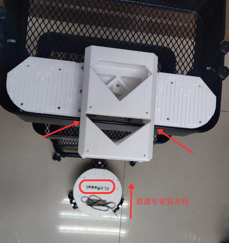
1、Place the chassis car directly under the cart, and note the installation direction of the chassis car (see the “XLerobot” lettering on the chassis)
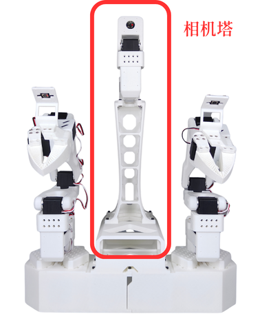
The installation positions of the camera tower base and the chassis car are shown in the figure
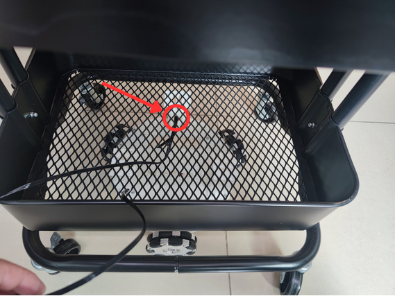
2、Pass the 90CM servo extension cable through the metal mesh of the cart
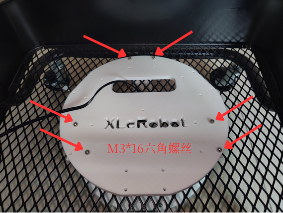
3、Use 6 M3*16 hex screws and 6 M3 nuts to fix the chassis car to the bottom of the cart
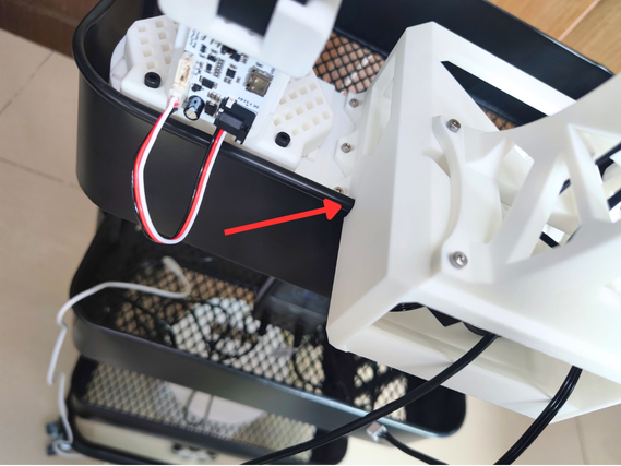
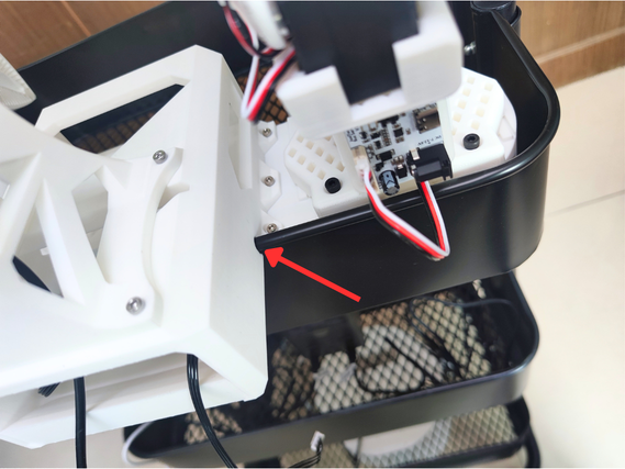
Install the Camera Tower Base
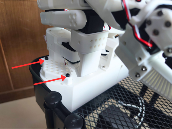
Note the grooves pointed to by the two arrows, and clip them onto the edge of the bottom layer of the cart
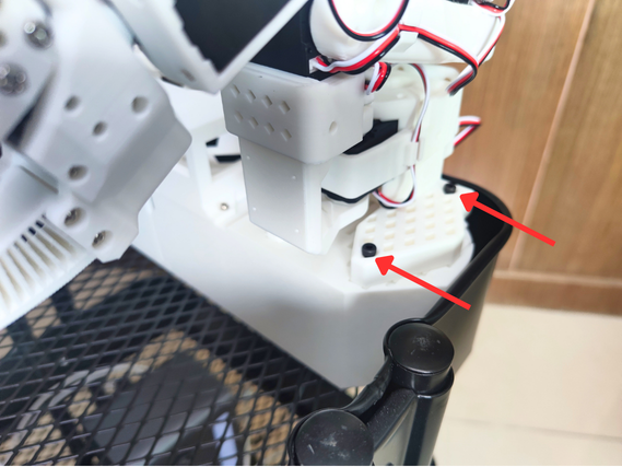
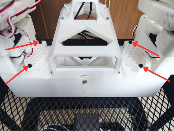
Fix the SO-ARM101 Follower Arms
Use 8 M4*30 hex screws and 8 M4 nuts to fix the two follower arms onto the camera tower base
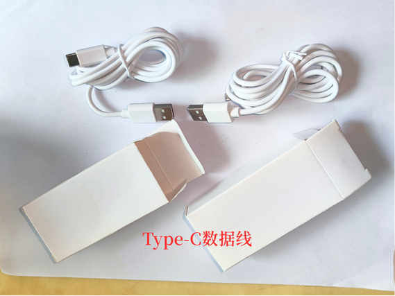
Connect the Data Cable to the Servo Driver Board
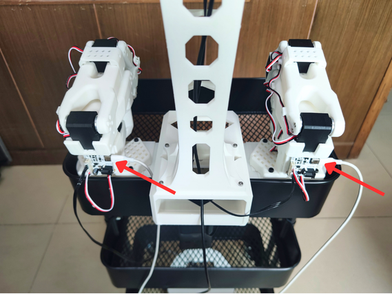
Connect the Power Cable to the Servo Driver Board
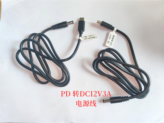
PD to DC12V3A power cable
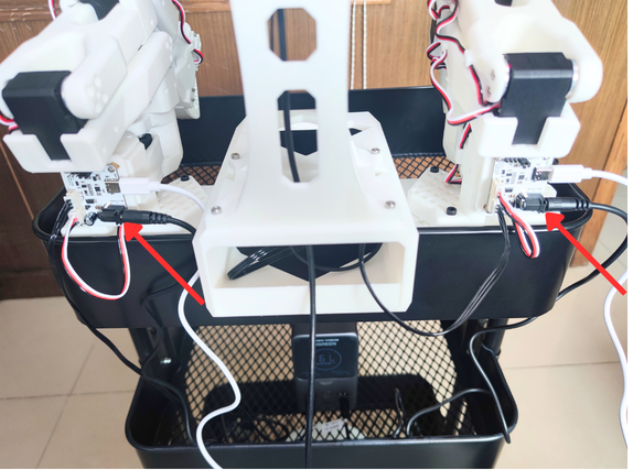
Servo Wiring
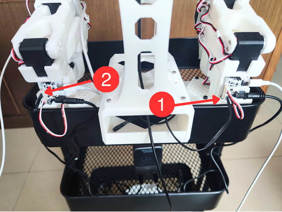
1、Connect the camera tower's 90Cm servo extension cable to the right servo driver board ①
2、The 90CM servo extension cable passes through two layers of metal mesh and connects to the left servo driver board ②
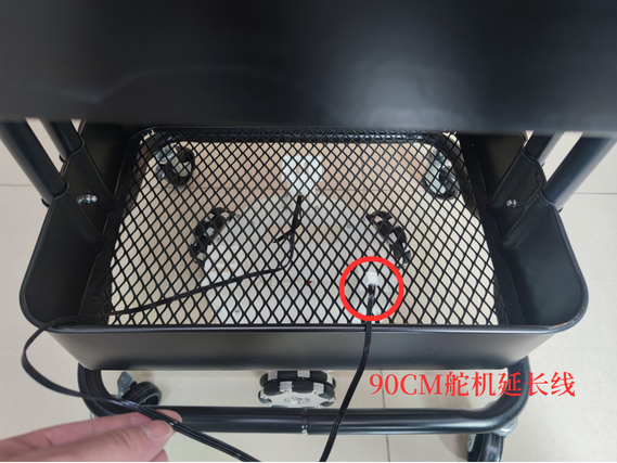
Connect the Camera to the Host Controller
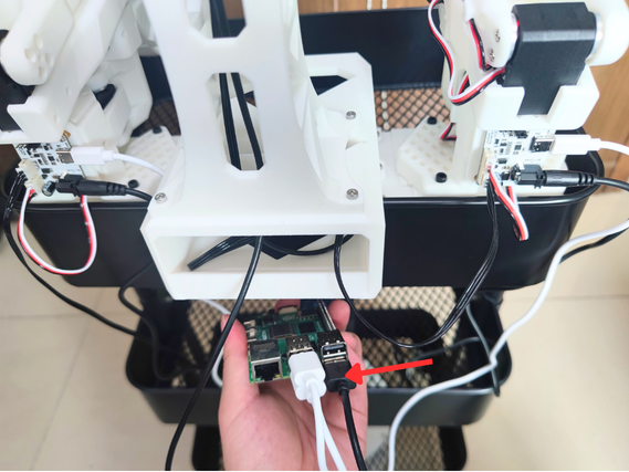
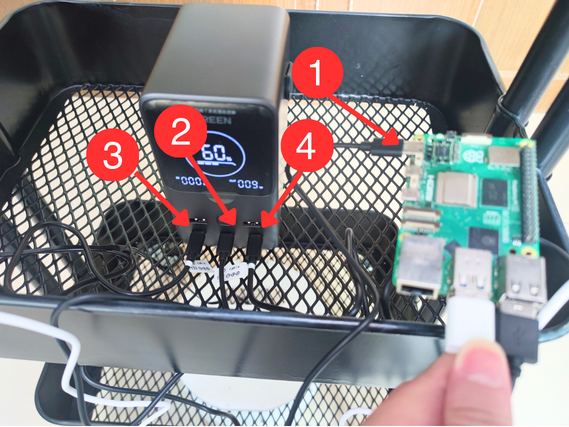
Power Bank Wiring Diagram
The power bank, Raspberry Pi, and PD 5V5A Raspberry Pi power cable must be purchased separately!
① PD 5V5A Raspberry Pi power cable
② Raspberry Pi power connector
③ Left servo driver board PD to DC12V3A power cable connector
④ Right servo driver board PD to DC12V3A power cable connector